100 kW / 215 kWh commercial solar and battery system
In short
This configuration pairs 100 kW of PV with a 100 kW hybrid converter and a 215 kWh battery. It suits commercial sites whose peak demand sits in the same range as the converter rating, with a limited set of circuits kept live during outages. It is not a whole-site off-grid solution for continuous loads above 100 kW, and it is not sized for loads whose starting current exceeds the converter overload window.
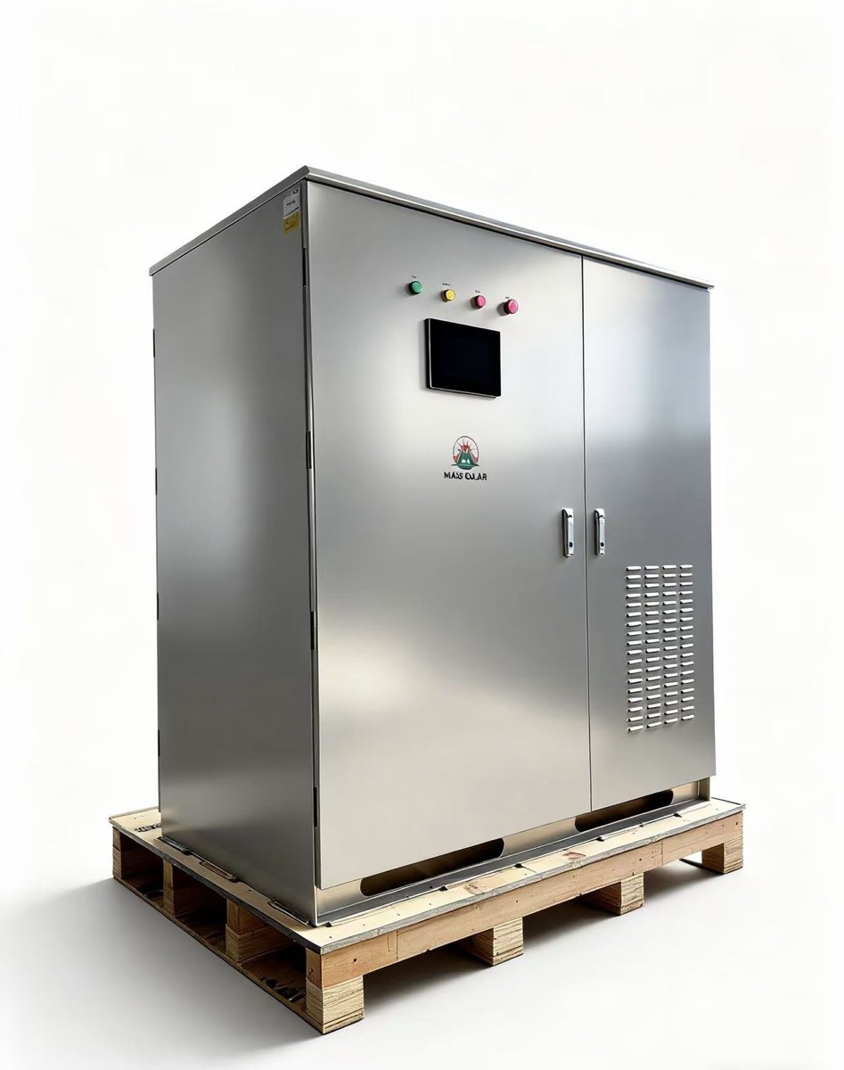
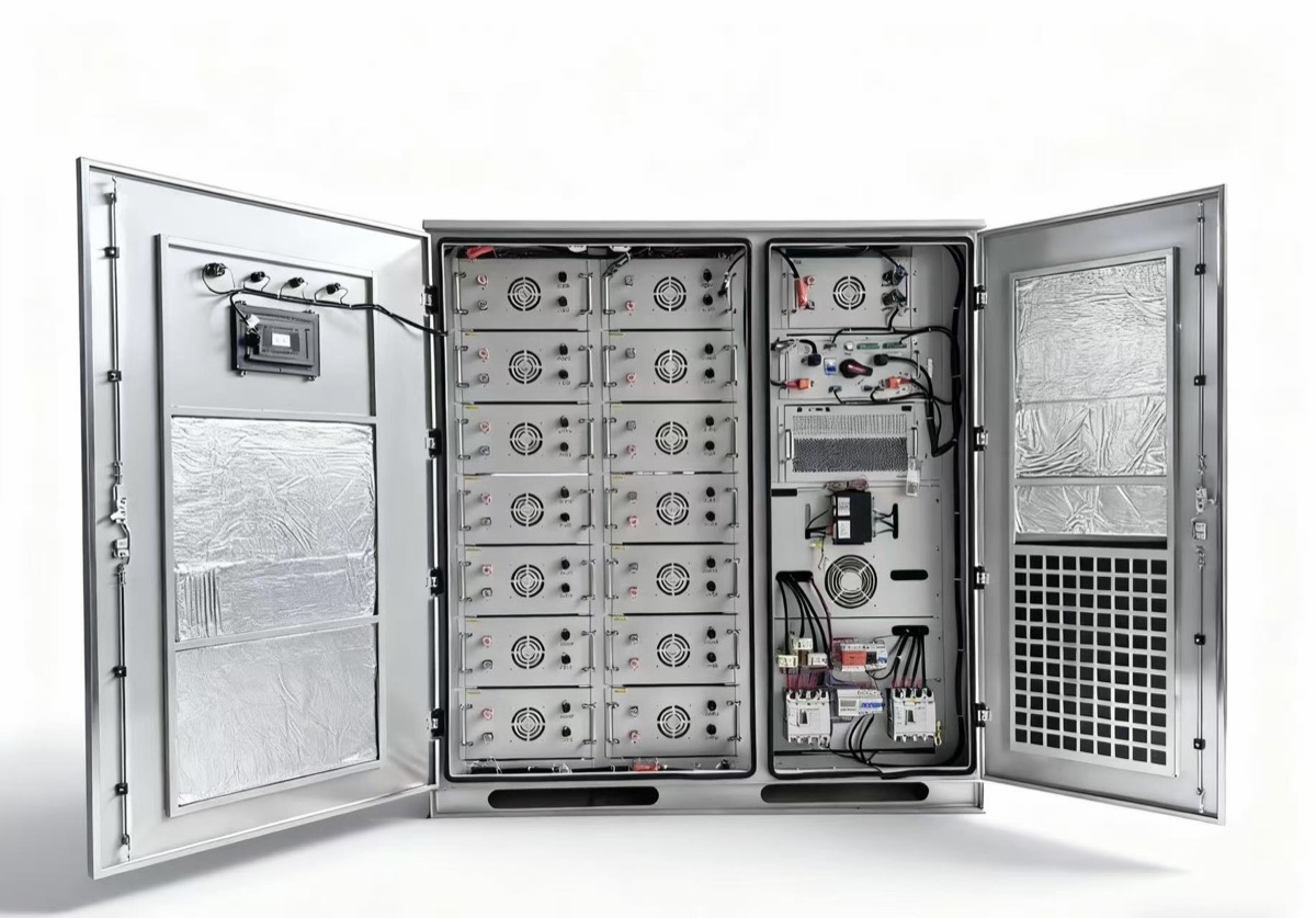
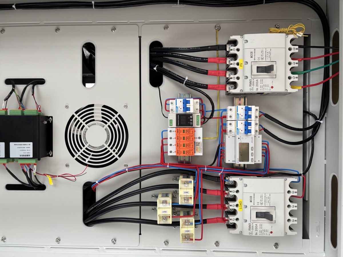
Appearance of the standard cabinet build. The shipped configuration, its datasheet and its documents are issued with the order.
1. Who this configuration fits
| Fits | Does not fit |
|---|---|
| Commercial site with peak demand at or below the converter rating | Continuous load above the converter rating — the design then needs a bypass or generator-supported path, sized separately |
| A defined set of circuits that must stay live during outages | A requirement to carry the whole site, including cooling, through an outage |
| Loads without large direct-on-line motor starts | Compressors or crushers starting at several times rated current |
| Grid-connected site where export is permitted or limited | Full off-grid operation for a continuous industrial process |
| Roof or ground area able to carry roughly 100 kW of PV | No usable area for PV — storage charged from the grid changes the economics |
If two or more rows in the right-hand column apply, this is the wrong starting point. See how we size a system.
2. What "100 kW / 215 kWh" means — and what it does not
The designation names the converter class and the battery energy. It does not by itself define the system around them:
- The storage cabinet is the core, not the whole system. A 100 kW / 215 kWh cabinet rating does not automatically include PV. Whether this configuration is ordered as a full solar-plus-storage supply or as storage only is decided in the quotation.
- PV coupling is a design decision. The reference design pairs PV on the DC side of a hybrid converter. The same battery class can also be built AC-coupled with separate PV inverters — the two topologies differ in protection, metering and commissioning, and the project single-line defines which one applies.
- Running functions follow the selected model. Grid-forming operation, bypass behaviour on overload and automatic backup transfer are functions of the specific PCS model and the site design — the quotation names the model and states which functions it carries.
Layer 1 — public base parameters
Enough to judge whether this configuration is worth a project inquiry. Every figure here is a nameplate or class value.
| Parameter | Public value | What it is |
|---|---|---|
| PV capacity | 100 kW | DC class of the reference design; module count depends on module wattage |
| Converter rating | 100 kW | Hybrid-class continuous AC rating; functional detail sits in Layer 2 |
| Battery nominal energy | 215 kWh | Nameplate, not usable — see the runtime worked example below |
| Battery chemistry | LFP | Chemistry class of the cabinet |
| AC output | Three-phase, 400 V class | Confirm against your site voltage during design |
| Grid interaction | Grid-tied, export-limited, backup | Export permission is a site condition, not a product feature |
Layer 2 — confirmed per project, with named models
These are set by an engineer against the actual equipment selection and issued in the proposal. They are not published as generic numbers, because each one moves with the model specified.
| Item | What gets confirmed | Confirmed how |
|---|---|---|
| Equipment models | Brand and model of PCS, battery modules, PV modules — labelled under the brand that made each | Bill of materials in the proposal |
| Usable capacity | Usable state-of-charge window for the selected battery model | Battery datasheet attached to the order |
| Conversion and overload | Peak efficiency curve, overload window and its duration for the selected PCS | PCS datasheet; motor-start check in design |
| Protection, cooling, environment | Ingress rating, cooling method, operating temperature and altitude range of cabinet and PCS | Datasheets per model; site conditions reviewed in design |
| Certificates | Certificate list that applies to the selected models, copied per certificate | Certificate copies in the document pack |
| Warranty | Term and claim process per component — modules, PCS, battery each carry their own | Written warranty terms attached to the quotation |
| Transfer and bypass | Backup transfer arrangement, transfer time and overload bypass behaviour of the selected model | PCS datasheet plus the project single-line diagram |
Layer 1 tells you whether to ask. Layer 2 is what you get before you sign — every row lands in the proposal, not after the order.
3. What is in the supply
Supplied by us
- PV modules and mounting structure
- Hybrid converter / PCS
- Battery cabinet with BMS
- DC and AC distribution and protection
- Cabling, connectors and accessories within the enclosure scope
- Monitoring gateway and platform access
- Test record, datasheets, as-built configuration table, packing list
Not supplied by default
- Civil works, foundations, cable trenches
- Site installation labour and lifting equipment
- Utility interconnection application and fees
- Import duties, taxes and customs clearance
- Local permits and grid-protection settings sign-off
Any of these can be added to our scope where we can legally deliver them in your market. The quotation states which model applies.
4. Price: where the cost sits, and how a quotation is built
There is no list price, because delivered cost moves with destination, duties, scope split and quantity. What we can show before you ask is where the cost sits. The table below is the structure of a delivered project of this class, anonymised and expressed as shares so it stays meaningful across markets:
| Cost block | Typical share of delivered cost | What moves it |
|---|---|---|
| PV modules | ~30–35% | Module wattage class and volume |
| Battery cabinet (LFP + BMS) | ~25–35% | Capacity; the largest single block on storage-heavy designs |
| Hybrid converter / PCS | ~10–15% | Rating and grid-forming requirement |
| Balance of system & mounting | ~8–12% | Roof vs ground mount, cable runs |
| Freight and insurance | ~8–15% | Route and destination port; the most variable block |
| Duties and taxes | Destination-dependent | Your tariff schedule — we list it as its own line |
| Design, testing, documentation | ~5–8% | Certification set required by your market |
How to read this table: the shares come from anonymised delivered projects of this class and are indicative, not a quotation. The absolute figure is built from the lines below, each marked included or excluded.
| Quotation line | What it tells you |
|---|---|
| Equipment | Itemised by subsystem, with model and quantity |
| Balance of system | Structure, cabling, protection, monitoring |
| Packaging and inland transport | To port of loading, stated separately from freight |
| Freight and insurance | Quoted to your named destination, not a generic Incoterm |
| Duties and taxes | Marked included or excluded — never left blank |
| Installation and commissioning | Excluded by default, quoted separately if required |
| Training and documentation | Listed with the deliverable named |
To price this configuration we need five inputs: destination country and port, quantity, scope split (equipment only or installed), required certification set, and delivery window.
Documents you can review before ordering
You do not have to buy first and read later. These are available on request, before any commitment:
| Document | What you get |
|---|---|
| Configuration datasheet | The full parameter set for this configuration, including the values left open above |
| Sample factory test record | An anonymised completed record, so you see the format and the acceptance values before you sign for them |
| Sample as-built configuration table | The document your EPC hands over at commissioning, filled for a past project of this class |
| Sample quotation | The quotation format below, filled in with anonymised figures |
5. How the system runs
Mode-by-mode behaviour (secondary detail — expand if you need it)
| Condition | What happens |
|---|---|
| Daytime, generation above load | Load is served by PV; surplus charges the battery, then exports if permitted and if export is enabled |
| Daytime, generation below load | Deficit comes from the grid, or from the battery depending on the dispatch setpoint |
| Evening, no PV | Battery discharges against a configured setpoint until the reserved state of charge is reached |
| Grid failure | Backup circuits transfer to the converter; non-backup circuits drop. This is a design decision made with you, not a product limit |
| Battery at reserve | Backup circuits return to grid or generator; the reserve level is set to protect outage capability |
Backup runtime: a worked example, with every assumption on the table
The theoretical figure is 215 kWh ÷ 100 kW = 2.15 hours — that is the ceiling before any losses. A realistic planning figure is lower, because four factors each take a portion of the nameplate energy. Here is the calculation an engineer on our side runs, with the assumptions stated so you can substitute your own:
| Step | Coefficient used | Energy remaining | Basis |
|---|---|---|---|
| Nominal capacity | — | 215.0 kWh | Configuration rating |
| Usable state-of-charge window | × 0.90 | 193.5 kWh | Reserve kept for battery protection and backup readiness |
| Converter efficiency at load | × 0.92 | 178.0 kWh | PCS conversion loss; lower at partial load |
| Temperature and ageing | × 0.95 | 169.1 kWh | High-ambient derating plus cycle ageing |
| Deliverable energy | — | ~169 kWh | What the load actually receives |
Applied to load: at a 100 kW continuous backup load this example gives roughly 1.7 hours; at a 60 kW evening load, roughly 2.8 hours. The coefficients above are engineering-typical values for this class, pending the model datasheet — your project figure is calculated from your actual load profile and confirmed against the datasheet before it goes into a proposal.
What to ask any supplier: "What usable state-of-charge window and converter efficiency did you assume, and at what load level?" The answers turn a theoretical division into a planning figure you can build an outage plan on.
6. Project references for this class
Configurations in this class have been designed and supplied into West Africa and Southeast Asia. These are the references we can discuss today in engineering terms — load profile, layout constraints, protection choices:
| Region | Scenario | Configuration | Status |
|---|---|---|---|
| West Africa | Hotel | 250 kW PV + storage | Reference configuration — delivery details on request |
| Southeast Asia | Cold storage | 135 kW PV + storage | Reference configuration — delivery details on request |
Client identities, photographs and measured results join this table wherever the customer has approved disclosure. Ask for the reference closest to your load shape and we will send the full configuration description.
Request a reference configuration7. Delivery, warranty and installation responsibility
| Item | Default position |
|---|---|
| Delivery | Named port or site, Incoterm stated in the quotation. Delivery window confirmed after configuration is fixed |
| Warranty | Per component: PV modules, converter and battery each carry their own terms and claim process, attached to the order |
| Installation | By your team or a local partner. Commissioning support and remote diagnosis included in technical support |
| On-site attendance | Quoted separately, only where we can legally provide the service in your market |
| Spares | Consumables and common replacement parts listed with part numbers; critical spares can ship with the main order |
8. Get a configuration for your load
Five fields. We only ask for what changes the answer.